














When should we use differential protection type B? What is the difference between a differential type F and a type B? Are the differential called «superimmunized» type B?
Contact with indirect means
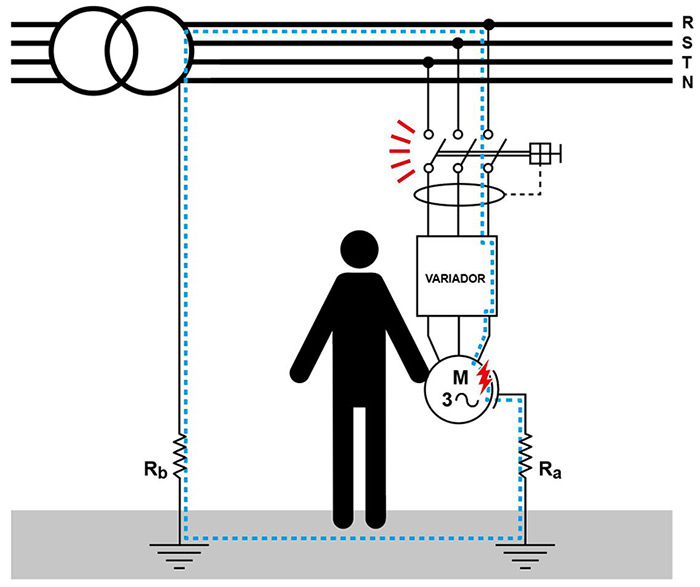
The devices of differential protection They are used to protect the facilities from contact Indirect connections. According to the Low Voltage Electrical Regulations (REBT), indirect connections are: “contact of people or domestic animals with parts that have become stressed as a result of a failure of isolation.”
Put more colloquially, it is when a person touches the chassis of a receiver, for example, a motor that has been energized due to a failure in the insulation. When this defect occurs, the device that detects it is a differential (usually), and since the receiver is grounded, a current diversion to the ground terminal occurs, whereby the differential detects a current difference and acts to disconnect the affected installation or part of the installation.
Therefore, we can already see that The differential protects the line that feeds the receiver from isolation defects, as well as the receiver itself. When the receiver is also involved in protection, problems begin to appear, or rather, the need for different types of differential protection.
Types of differentials
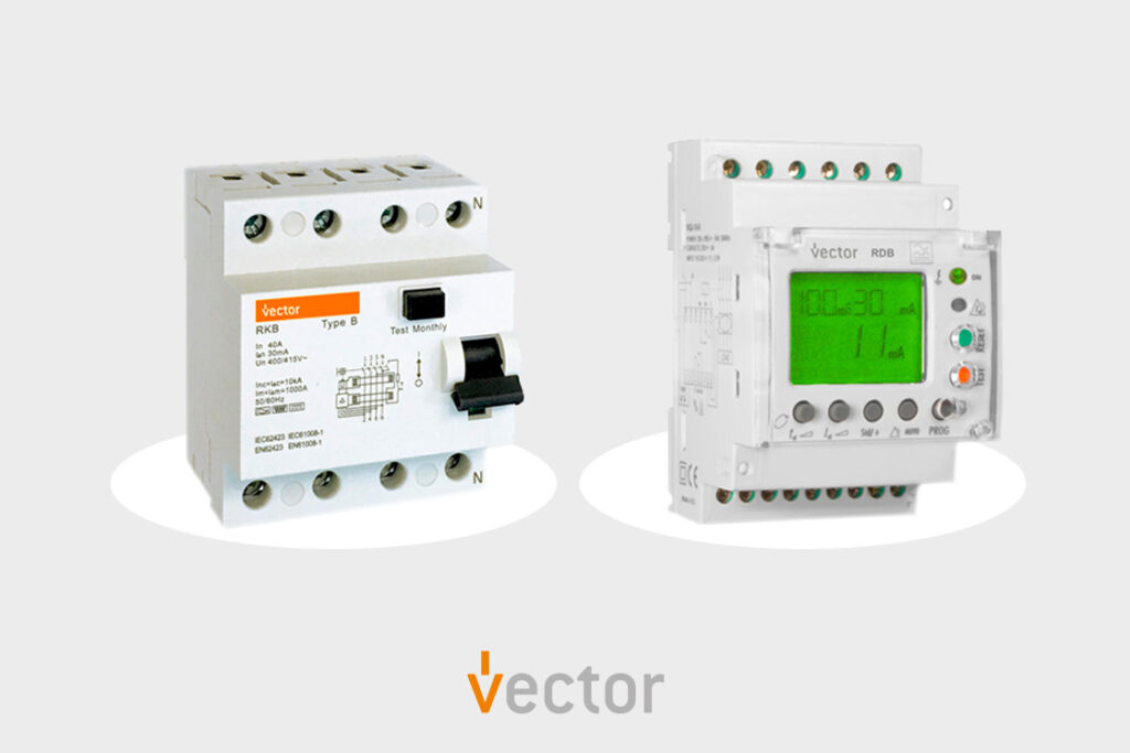
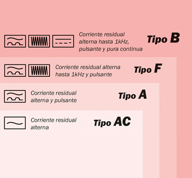
There are 4 types of normalized differentials on the market: Type AC, Type A, Type F and Type B. Each type of differential has its own symbol and is capable of detecting different types of differential currents. In fact, the symbol already practically tells us what type of current the differential is capable of detecting.
AC type differential:
It only detects differential sine waves of 50Hz.
Type A differential:
Detects senoidal and pulsed signals, in both polarities.
Type F differential:
It is capable of detecting 50 Hz sine and pulse signals with mixed components up to 1000Hz.
Differential type B:
It detects the same thing as a type F but by adding signals from pure DC components.
Regarding the doubts about the so-called “super-immunized differential,” the answer is that this type of differential is not standardized; each manufacturer calls it differently and they are usually always of type A. In fact, type F is the standardization of these differentials, and different brands are already starting to replace their super-immunized products with type F ones.
Types of receptors
Between a differential and a receiver there is always an power line. If the isolation of this line fails, the current that would be drawn to ground is always sinusoidal, just like the voltage of the electrical grid and, therefore, of the same frequency (50Hz), so we can determine that the AC-type differential always protects our lines.
But the differential also protects the indirect contacts of the receivers. Below are detailed the different types of receivers and what type of leakage current they generate when an insulation defect occurs:
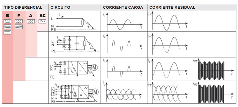
Receivers that include electronics (and basically an AC-to-DC rectifier) in the event of an isolation failure, the current that is derived to ground is no longer sinusoidal.
Rectifying receivers generate different types of fault currents depending on whether they are single-phase or three-phase:
· Single-phase receivers:
They generate pulsed fault current. Therefore, they require differential protections type A or F.
· Three-phase receivers:
They generate continuous fault currents (DC). Therefore, they require B-type differential protection.
Another aspect to consider is the what happens when we have a speed controller and the defect occurs downstream of the controller, in the cable that feeds the motor or in the motor itself.
What type of fault current is produced? Is it related to the frequency we apply to the motor? Or does the line frequency, 50Hz, appear? Or is it the switching frequency of the variator at the order of kHz?
The answers to the previous questions are that the defect current is composed of:
· The network frequency of power supply, that is, the 50Hz.
· The Operating frequency of the motor, that is between 0-1000Hz.
· The switching frequency from the PWM controller, at the order of 8kHz.
The switching frequency of the inverter, the PWM signal, if the inverter has the EMC filter in its input, as recommended, its value will be very attenuated compared to the other two frequencies.
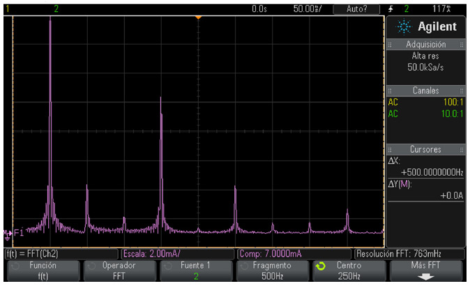
What will be the result of mixing a 50Hz signal with another, for example one of 200Hz? Well, it is a mixture of frequencies, where when viewed in time, the 200Hz signal is seen to be modulated in amplitude at 50Hz.
Image of the current leakage spectrum of a variator with an insulation failure and operating at 200Hz. The first signal on the left is the 50Hz signal, and the second signal in amplitude is the 200Hz signal.
Are there differential amplifiers capable of operating with this type of fault current? Yes, the differential amplifiers that have been manufactured to respond to this type of signal up to 1000Hz are the F and B types.
EMC Filters
So far we have seen the types of leakage or defect currents that can appear in an installation when an insulation defect occurs in different parts of the installation, including the receivers. Now Let's look at the natural flow of migration from an installation, or in other words: the leaks that exist without any insulation defects.
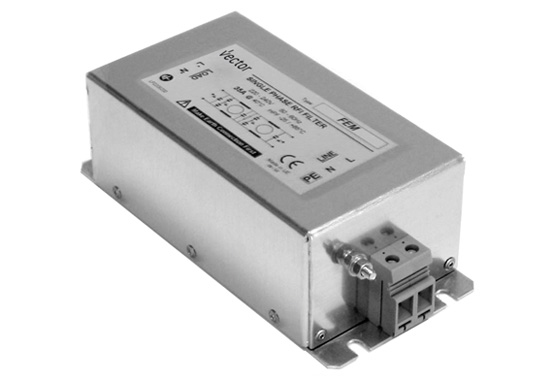
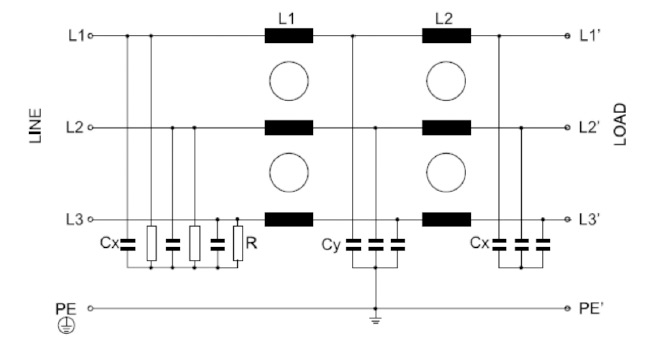
The responsible parties for such leaks are the EMC filters., acronym for “ElectroMagnetic Compatibility”. These filters essentially they prevent the electronic equipment from disturbing the other teams They are connected to the electrical network, but to perform their function they need to have “Cy” capacitors connected between the phases and the ground, and therefore these capacitors produce a permanent leakage to the ground, which must be taken into account.
We see the Typical schematic of an EMC filter, where we can observe the Cy capacitors connected between phases and ground.
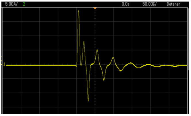
Another factor to consider is what happens when a receiver that incorporates this EMC filter is powered up. If we analyze the transient, we will see that a current spike occurs at the ground and that this depends on the instantaneous voltage of the network at the time of connection.
In this image, the horizontal scale is 50us, and the vertical one is 5A per frame; that means that the transient reaches values of 20A, but it lasts for less than 20us.
This aspect is also taken into account by the spreads. Type F and B, which, when detecting this ground current spike, should not detect it, and therefore should not disconnect or “fire” it.
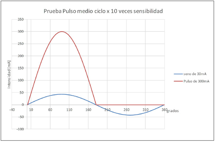
Below we detail one of them. Tests those to whom they are subjected differences in order to be marked as type F or B.
The differential is tested with a current that lasts half a cycle, 10ms, with a peak current 10 times the sensitivity of the differential; let’s take an example of a 30mA differential being tested with a peak current of 300mA, which lasts 10ms; the differential should not jump (red signal).
We must bear in mind that a differential of 30mA, such as AC or A, with the blue color signal usually jumps between 5ms and 20ms.
Sensitivity and timing
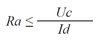
The The minimum sensitivity of a differential goes hand in hand with the value of the grounding of the installation., Ra, and the contact voltage according to the regulations is 50V in dry rooms and 24V in humid rooms. Under normal conditions, or rather with AC and A-type differentials, the following equation must be respected:

Where:
Id= sensitivity of the differential in [A]
Uc= contact voltage 50/24 [V]
Ra= Grounded value [O]
But for F and B-type differentials, where it is expected that signals of up to 1000Hz may appear, Since the sensitivity of the differential is not the same at 50Hz as at 1000Hz, the above equation must be verified for the larger current corresponding to the highest frequency.
Unless the manufacturer specifies lower values, The firing current at 1000Hz can be up to 14 times higher than at 50Hz, with the above equation being modified as follows:

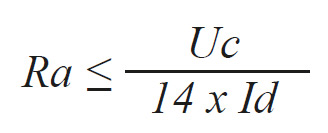
In conclusion, such differentials require much lower ground wire values.
Response times
According to the standard UNE-HD 60364-4-41:2010, the maximum trigger times for TT networks are:
· For terminal lines less than 32A, the maximum firing time is 0.2”
· For lines over 32A and distribution lines, the maximum firing time is 1”
· The instant or general spreads and the Selective ones comply with the 0.2” time limit”
Serial assembly
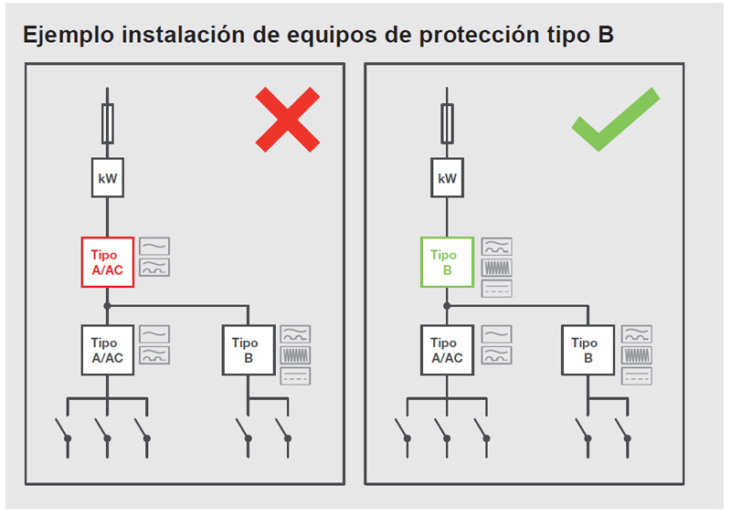
When differential pairs are installed in series, selectivity must be ensured., by legal obligation of REBT ITC-BT-17 section 1-2, this is achieved by fulfilling three conditions:
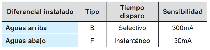
· The sensitivity of the differential installed upstream must be 3 times greater than that installed downstream.
· The trigger time of the differential installed upstream must be greater than the trigger time of the differential installed downstream.
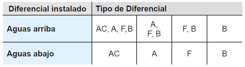
· The type of differential installed upstream must be greater or equal to the type of differential installed downstream.
The following table shows all the combinations depending on the type of differential installed downstream.


Example of a concrete assembly with sensitivity values, time and type:

Conclusions and links
It is evident that electronic receivers with three-phase input and that rectify the alternating current to direct current must have B-type differential protection, because the other types of differential protection do not guarantee that they will act in the event of a fault.
In addition to protecting in all situations, the B type differential prevents untimely firing due to transient connections of the EMC filters.
Generally speaking, Frequency inverters, SAIs, UPSs and chargers for electric vehicles, with three-phase power supply should be protected with B-type differential protection. Otherwise, they will not be properly protected with regard to indirect contacts.
Author:
JOAN ROMANS ARTIGAS (Linx Engineering)
Electronic Engineer
Technical Engineer of Telecommunications
Download the article in PDF
Please view the article in a PDF file by filling out the following form with your details to access the download link: